


'91 Magna Elite Steering wheel Controls
The Magna Elite uses an uncommon method for sending codes to the radio. Rather than a voltage divider, it uses an NEC microchip that is intended for infrared remotes. Because of this, it is easy to work with if you have the right tools. The remote wire is connected to a transistor, which pulses to ground. The signal is usually around 10v, and only 10ma.
The low current makes it perfectly safe to wire an LED to, and it actually barely has enough power for that. That only applies if the transistor output is used as the LED negative. As a rule, never connect an LED without an appropriate resistor to limit current. 2.4v is ok but anything higher could destroy them.
You will need:
A radio with an infrared remote control (or an Alpine CDE-164EBT radio)
1x Arduino (works fine with nano, ATMega328P)
2x IR transmitters, i recommend 1 50ma and 1 20ma or less for the swc controls
1x IR receiver (demodulator? 38KHz)
1x 12v to 5v voltage regulator, or a quality USB adapter is recommended
I also recommend a project box, and a breadboard if you use a micro or nano.
Heatshrink is essential, since the IR component wires are quite close together
This is best suited to an Arduino nano, unless you know what pins to use to transmit IR with.
This SWC decoder/transmitter works by receiving and decoding the IR codes from the steering wheel controls, then transmitting aftermarket radio codes.
To begin with you could solder the LED (50ma or less) to some wire, 2 core, 4 core, just whatever you have. Heatshrink is nesessary, as this LED can then be mounted under the cover that sits above the climate control. That cover simply pops off. The LED can comfortably be wedged between the metal bracket, and the woodgrain garnish. Remember to aim the LED downwards, and position it vertically in line with the receiver on the radio. this can be seen in daylight as a small discoloured patch (usually dark purple). This LED will be wired to the Arduino digital pin 3 for an ATMega 328P. The LED should be grounded to the Arduino, but you can often get away with wiring it to earth. It may introduce noise issues, though. You should remove the center console, and the cigarette lighter / electric mirror / radio garnish. Then you can run the wires.
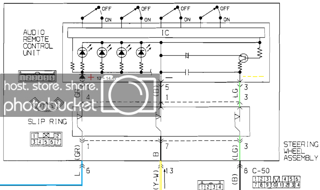
Next, you will need to wire up the IR receiver and the other LED (low current). IR LEDs from old remotes are perfect, as long as there not tinted. These need to point at each other. If you can find a small connector that has lots of pins, the LED and receiver may just plug into the connector for a convenient way to mount them. Connectors on old computers are perfect, and already have wires so you won't have to solder the leads. The signal wire from the IR receiver can go to any digital pin, but if you don't know how to change the programming in Arduino IDE, you could just use pin 2. The LED that faces this receiver should be wired to +5v from either the regulator or from the Arduino, but may also be wired to the car's positive ~14.4v. This is allowed because the negative goes to the steering wheel controls. Don't worry, the LED only gets about 10ma because the SWC limits the current. Voltage is not really an issue for LEDs if the current is very low. If the LED doesn't light, use 14.4v and connect negative to the light green wire. Most cameras can see IR LEDs, and that's a brilliant way to test if it works. You must not wire the LED negative to vehicle negative and vehicle positive (without a proper resistor), and you don't need to in this situation.
The wire is usually a pale green, also with grey and black wires in the same plug.
With all that out the way comes the programming part. For this, you will need to download the Arduino IDE and IRLib. A little background knowledge of computers and Arduino is highly recommended.
Once you have IRLib, you will need to copy it to the libraries folder, possibly C:\Program Files (x86)\Arduino\libraries, then go into it and find examples. Then upload IRrecvDump and you can find the codes for your remote by using the serial monitor. You will just need to have the IR receiver connected, and change the pin number in the sketch.
You will need 4 codes from the remote, they can be any button you wish. I used volume up, volume down, source and the skip button for convenience. These codes will need to be entered in the sketch I provide, in place of the codes that look like 0x614E28D7. Note that the first 4 codes you see in the sketch should not be changed, as these are the codes detected for the steering wheel controls. They only need to be changed if your controls send different codes.
Hopefully this is enough information for you to wire your own controls, but you are quite welcome to ask me about anything you need help with.
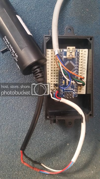
Here is the only photo i took during the process:
Note that the breadboard was cut with a hacksaw, then trimmed with the wire brush on a grinding wheel. For the pins, I took them out of pin headers. then I put each pin in a breadboard offcut. This made it easy to wrap wire around them, for soldering. Heatshrink was also used, and is essential.
HTML Code:#include <IRLib.h> #define VOL_UP 0xA9D7295A #define VOL_DOWN 0xF3ABCCBC #define SEEK 0xDEA73B7E #define AMFM 0x87BD05F2 //IR Transmit pin 3 default, 9 alternative by editing IRLibTimer.h IRsend My_Sender; int RECV_PIN = 2;//Receive on pin 2 IRrecv My_Receiver(RECV_PIN); IRdecode My_Decoder; IRdecodeHash My_Hash_Decoder; void setup() { My_Sender.send(NEC,0x614EA857, 32); My_Receiver.No_Output();//Turn off any unused IR LED output circuit My_Receiver.enableIRIn(); // Start the receiver // Serial.begin(9600); // delay(2000);while(!Serial);//delay for Leonardo // Serial.println("Begin"); } void loop() { if (My_Receiver.GetResults(&My_Decoder)) { My_Hash_Decoder.copyBuf(&My_Decoder);//copy the results to the hash decoder My_Decoder.decode(); My_Hash_Decoder.decode(); switch(My_Hash_Decoder.hash) { case VOL_UP: My_Sender.send(NEC,0x614E28D7, 32); //Serial.println("up"); My_Receiver.enableIRIn(); //blink(); break; case VOL_DOWN: My_Sender.send(NEC,0x614EA857, 32); //Serial.println("dn"); My_Receiver.enableIRIn(); //blink(); break; case SEEK: My_Sender.send(NEC,0x614E48B7, 32); //Serial.println("sk"); My_Receiver.enableIRIn(); //blink(); break; case AMFM: My_Sender.send(NEC,0x614E50AF, 32); //Serial.println("fm"); My_Receiver.enableIRIn(); // blink(); break; } My_Receiver.resume(); } } /* void blink() { digitalWrite(13,HIGH); delay(10); digitalWrite(13,LOW); }*/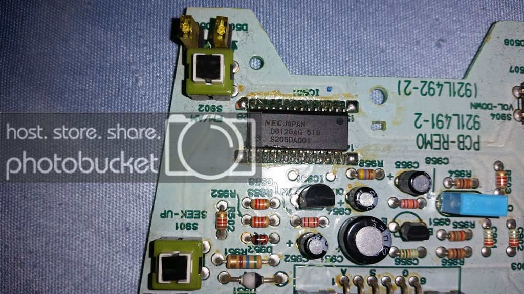
 Reply With Quote


